A Line Following robot is a popular beginner-friendly tutorial for all microcontrollers. It is a simple and fun way to learn to code. In this blog, we will see how to build a line follower robot using Raspberry Pi Pico Microcontroller and Python.
Working Principle of IR Proximity Sensor:
Black is the color that absorbs light and all other colors reflect some light back based on their color (most reflecting color is pure white). Every color has a wavelength, our eyes can be visible only in a specific range of wavelengths only. One example of an invisible wavelength for our eyes is called Infrared Light. We can’t see infrared light with our naked eyes (but can by our mobile phone with poor IR Filters).
IR Proximity Sensor or Infrared Proximity Sensor is a kind of proximity sensor that has an IR Transmitter LED and an IR Receiver LED. The transmitter LED emits an Infrared Light and the receiver LED senses infrared light. So, there will be no reflection when there is no object (or) black object in front of an IR Proximity Sensor. However, if there is any other color, the infrared light gets reflected back by the surface to the IR Receiver LED.
By the above Infrared Principle, we can make a robot that can sense the black line and keep it away from the black line on both sides, so that it will stay on the line.
Components Required:
- Raspberry Pi Pico
- IR Proximity Sensor x 2
- Tiny Breadboard
- Jumper Wires
- L298N Motor Driver
- 2WD Chassis Kit (Motor, Wheel, Chassis)
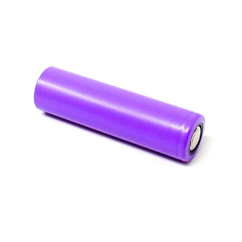
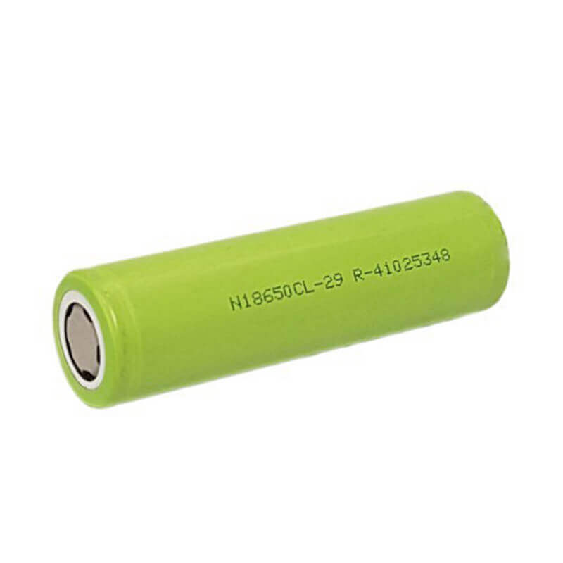
- 18650 Battery x 3
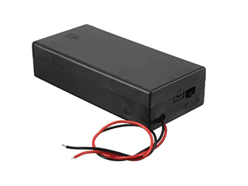
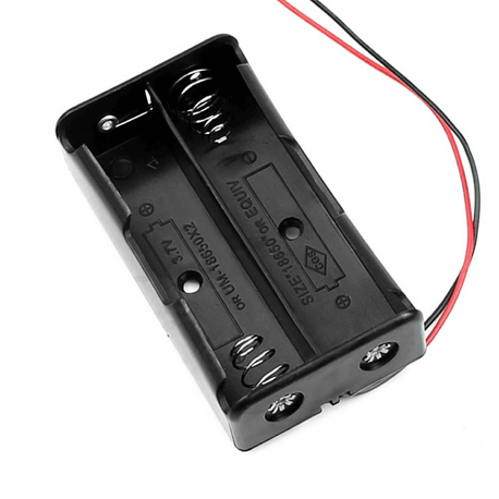
- 3 Cell 18650 Battery Holder
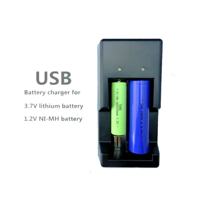
- Lithium Battery Charger (Optional)
Useful Resources:
- Raspberry Pi Pico Pinout
- Raspberry Pi Pico Documentation, Design Files, etc
- Getting Started with Raspberry Pi Pico
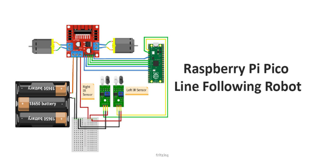
Circuit Diagram for Line Following Robot:
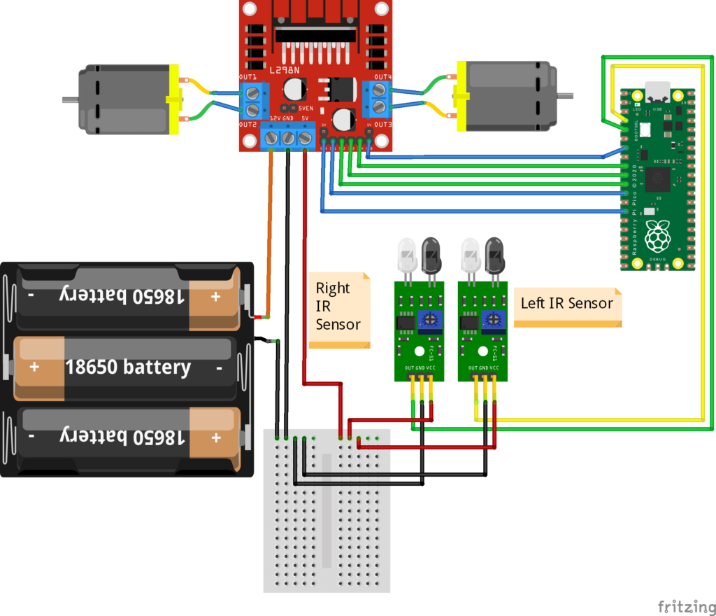
Note: If you are using 4 Wheel Drive, You can connect the motors in parallel on each side. As we are using an L298N driver (2Amps Max Current), it can handle 4 BO Motors (Yellow). When mounting on the chassis, the left two motors are from M1 and the Right two motors from M2. This way both wheels run in the same direction. You can check the video for a reference of rotation.
Line Follower Robot Code (Python – Raspberry Pi Pico):
from machine import Pin,PWM #importing required PIN and PWM from modules
import time #importing time module
import utime

#Define and map Pico pins with L298N Motor Driver Pins as OUTPUTS
IN1=Pin(9,Pin.OUT)//IN1 Motor Driver
IN2=Pin(8,Pin.OUT)//IN2 Motor Driver
IN3=Pin(7,Pin.OUT)//IN3 Motor Driver
IN4=Pin(6,Pin.OUT)//IN4 Motor Driver

# Defining enable pins and PWM object
EN1=PWM(Pin(10))// Enable Pins used for PWM Speed Control
EN2=PWM(Pin(5))//Enable Pins used for PWM Speed Control

#Set Pins for IR Sensors as INPUTS
right_ir = Pin(3, Pin.IN)//Right IR Sensor
left_ir = Pin(2, Pin.IN)//Left IR Sensor

#Set PWM Switching Speed in Hertz for EN Pins
EN1.freq(1000)
EN2.freq(1000)

#PWM Duty Cycle
EN1.duty_u16(65025)//Maximum for Pico 65025
EN2.duty_u16(65025)//Maximum Pico 65025

# Move Forward
def move_forward():
    IN1.low()
    IN2.high()
    IN3.high()
    IN4.low()

# Move Backward
def move_backward():
    IN1.high()
    IN2.low()
    IN3.low()
    IN4.high()

#Turn Right
def turn_right():
    IN1.low()
    IN2.high()
    IN3.low()
    IN4.high()

#Turn Left
def turn_left():
    IN1.high()
    IN2.low()
    IN3.high()
    IN4.low()

#Stop
def stop():
    IN1.low()
    IN2.low()
    IN3.low()
    IN4.low()

while True:

    right_val=right_ir.value() #Read Sensor 1 Value
    left_val=left_ir.value() #Read Sensor 2 Value

    print(str(right_val)+"-"+str(left_val))

    #Set Conditions for Obstacle Avoidance
    if right_val==0 and left_val==0:
        move_forward()
    elif right_val==1 and left_val==0:
        turn_right()
    elif right_val==0 and left_val==1:
        turn_left()
    else:
        stop()
Upload and AutoRun the Code on Pico:
You can save and run this file locally by any name. But if you want to auto-run your code on Raspberry Pi Pico, the name should be main.py only. You can save the file by clicking File> Save As > then select Raspberry Pi Pico on the popup (Pico should be connected). Then save the file as main.py
We have to draw a black line using black chart paper or black tape (avoid reflecting/shiny tapes). We will be placing the sensors away from this line. One on the left and another on the right side of the line.
Note: Most digital sensors will be in HIGH State(1) at normal conditions and LOW State(0) when something is detected. This is because electrical noises in the surrounding causes false trigger. To avoid this, Pull-Up resistors are used in most of the sensors.
The function of the code and Robot:
Forward Sensing: By default, the white surface on both sides, both sensors detected (LOW, LOW), and the motors run in the forward direction.
Right Sensing: When the Right Sensor is detected the black line (LOW, HIGH), the motor rotates in the Right direction.
Left Sensing: When Left Sensor is detected the black line (HIGH, LOW), the motor rotates in the Left direction.
Stop: When Both Sensors detected the black line (HIGH, HIGH), the motors stopped.
Sensor Logic:
| Function | Left Sensor | Right Sensor |
|---|---|---|
| Forward | LOW | LOW |
| Right | LOW | HIGH |
| Left | HIGH | LOW |
| Stop | HIGH | HIGH |
Motor Logic:
| Function | IN1 | IN2 | IN3 | IN4 |
|---|---|---|---|---|
| Forward | LOW | HIGH | HIGH | LOW |
| Right | LOW | HIGH | LOW | HIGH |
| Left | HIGH | LOW | HIGH | LOW |
| Stop | LOW | LOW | LOW | LOW |
By this logic, the robot follows the line until the line ends.
Tips:
If your motor runs in the opposite direction, there are multiple ways to correct it. You can change the pin numbers on the code, Interchange Terminals of the Motor. Below is how to change via interchanging terminals.
- You can interchange motor terminals on M1 (or) M2 in the motor driver. Important! You must interchange terminals on the same side only. Do not connect one terminal to M1 and another terminal to M2. Otherwise, it will create a short circuit and can damage the L298N Driver.
- If your sensor detects the opposite direction, the simplest way is to interchange the mounting of sensors without any changes in wiring or code.
Recommended Batteries and Chargers for robots:
Motors consume more power, so it is recommended to use Lithium Ion Batteries for the best performance, recharging, and long shelf-life. The BO Motors we use is rated at 3-12Volt DC, 40-180mA. For our robot, 7-12V is recommended for better performance. You can use a cheap 9v battery, but it will not last long and is not rechargeable. So go with rechargeable lithium-ion batteries.
Lithium batteries connected in series add up the voltage, for example, 1 lithium cell’s nominal voltage is 3.7 Volt, and for the 7.4 Volt requirement, you need a 2 Cell 18650 Holder. For our robot, this is enough. So you can use a 2Cell or 3 Cell Holder. Below are the recommended battery and its accessories,

All Products Pricelist from Various Shops:
- SYB-170 Mini BreadBoard 170 Tie Points — Rs. 39
- Li-ion Battery Holder 2 x 18650 — Rs. 45
- Li-ion Battery Holder 3 x 18650 — Rs. 53
- TCRT5000 Dual Channel Line Follower sensor — Rs. 60
-
Electronic spices 2 x 3.7V 18650 Battery Holder, Battery Holder Case Wire...
—
Rs. 87
Rs. 149 -
iCSTORE - Breadboard Small/Mini Kit/Module, Solderless Prototype Bread Board...
—
Rs. 99
Rs. 199 -
ApTechDeals Jumper Wires Male to Male, Male to Female, Female to...
—
Rs. 99
Rs. 499 -
Sunrobotics 18650 x 2 Battery Holder With Cover and On/Off Switch
—
Rs. 125
Rs. 249 - L298N Motor Driver for Arduino — Rs. 125
-
Xcluma L298N DC Stepper Motor Driver Controller Arduino Pic Robotics Car Projets
—
Rs. 221
Rs. 290 - 2WD Robot Chassis Kit Acrylic — Rs. 369
-
PrimeRobotics CT-PS-2WDKIT 2Wd Smart Robot Bot with Chassis, Bo Motor,...
—
Rs. 379
Rs. 700 -
REES52 Raspberry Pi Pico microcontroller Development Board with Versatile...
—
Rs. 499
Rs. 799 - Raspberry Pi Pico W (soldered headers by FactoryForward) — Rs. 679
- Raspberry Pi Pico — Rs. 472
- Raspberry Pi Pico — Rs. 348
- Raspberry Pi Pico — Rs. 348
- 18650 Lithium Ion Battery 2900mAh (3C) - BAK BIS Approved — Rs. 206
- 18650 Rechargable Li-ion Battery 1200mAh — Rs. 59
- Tomo V6-2 Intelligent Battery Charger for 3.7v and 1.2V AA / AAA / 18650 /... — Rs. 449
- Jumper Wire All Set (M-M,M-F,F-F) 40PCS Each — Rs. 175
- 18650 Rechargable Li-ion Battery 2200mAh — Rs. 105